Q7
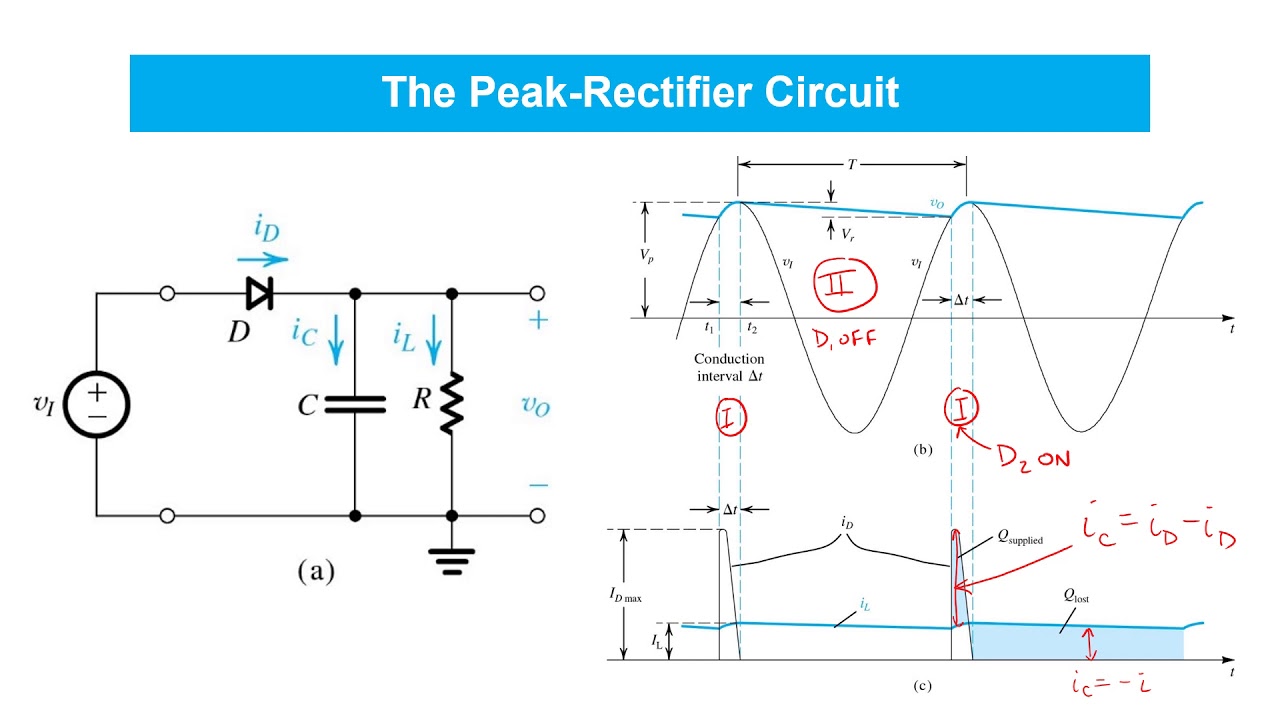
(a) By means of a schematic circuit diagram illustrate the peak rectifier, if the supply voltage is v(t) = V Sin wt, what is the voltage across the load resistor?
(6)
(b) A series circuit comprising a 50Ω resistor, a coil having resistance and inductance and a capacitor is connected across a 50 V variable frequency supply. When the frequency is 400 Hz the current reaches its maximum value of 0.6 A and the voltage across the capacitor is 200 V. Calculate EACH of the following:
(10)
(i) the value of the capacitance;
(ii) the resistance and inductance of the coil;
(iii) the power taken from the supply;
(iv) the circuit power factor.
Reference Answer
### Part (a): Peak Rectifier #### Concept and Operation A peak rectifier, also known as a peak detector, is a circuit designed to capture and hold the peak value of an alternating input voltage. The fundamental circuit consists of a diode, a capacitor, and a load resistor. 1. **Charging Phase**: The input voltage is given by $$ v(t) = V_{peak} \sin(\omega t) $$. When the input voltage rises during the positive half-cycle and exceeds the voltage across the capacitor, the diode becomes forward-biased and acts like a closed switch. Current flows, charging the capacitor. The capacitor charges rapidly towards the peak value of the input voltage, $$ V_{peak} $$.
Full answer on MeoMock — surveyor-grade reference answers for 7,000+ written exam questions.