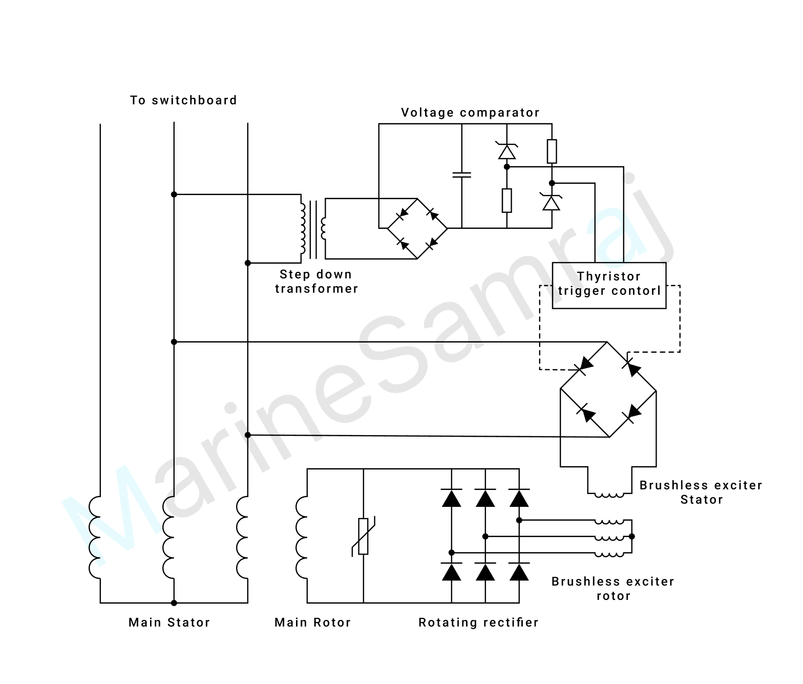
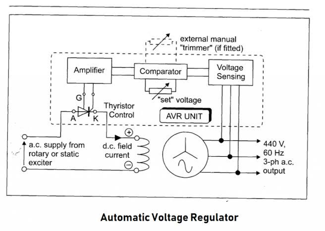
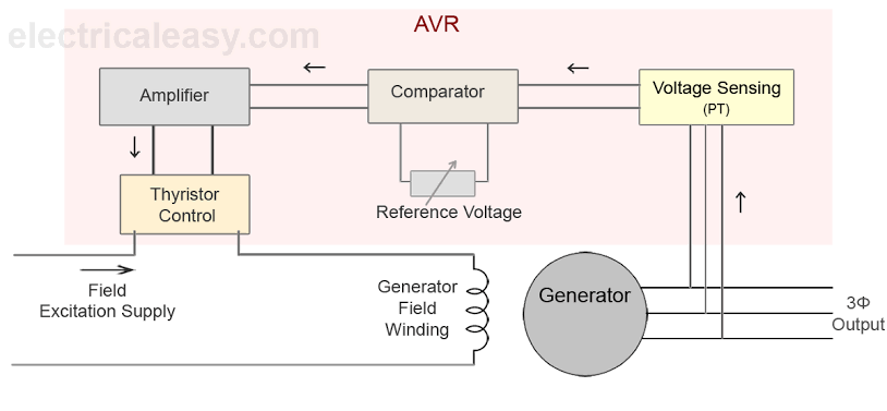
← MeoMock / Written exams
Class 2 (2nd Engineer) MET 📅 Mar 2019

Exam Question

(a) Sketch a circuit diagram for an automatic voltage regulator illustrating how the A.V.R. utilizes a silicon-controlled rectifier to control the excitation system for an alternator.

(b) Describe how the A.V.R. monitors output and controls the excitation system.

Exam question diagramExam question diagramExam question diagram

Reference Answer

(a) The terminal voltage is sensed by a 3-ph star-delta stepdown transformer and rectifier to D.C by a 3-ph bridge rectifier bank and smoothened by an L-C filter to represent the actual terminal voltage in a reduced D.C form. This voltage is compared in a Zener reference bridge circuit with the desired voltage provided by the Zener breakdown voltage so that the output gives the error or deviation between the two ( voltage difference between actual and desired value). This error voltage is utilised for the thyristor trigger control in the diode bridge. This thyristor diode bridge is provided with an A.C supply and the output depends on the conduction period of the thyristor which is triggered by the error voltage as mentioned earlier. The output from the thyristor diode bridge goes to the A.C exciter field of the alternator which in turn includes A.C voltage in A.C exciter 3-ph armature winding. This voltage is rectified by a bridge rectifier mounted on the rotor shaft and finally provides excitation for the main alternator field winding. This will generate a 3-ph AC voltage in the main armature winding.
(b) The magnetic field crossing conductors produce relative motion between the two. The magnetic field is created by the field windings of the generator. The conductors are the armature windings of the generator. The relative motion of the magnetic field across the conductors is provided by the rotor shaft. The more magnetic field lines cross conductors the more current is induced in the conductors. The way you get more magnetic field is to put more current through the magnetic field windings so if you want more voltage induced you need to apply more current to the field windings, and If output voltage drops, the AVR applies more current to the field windings, if output voltage increases because of reduce load the AVR reduces current to the field windings
An Automatic Voltage Regulator (AVR) regulates the generator terminal voltage by controlling the amount of current supplied to the generator field winding by the exciter.
The AVR controls the alternator output voltage by automatic adjustment of the exciter stator field strength. The AVR provides closed-loop control by sensing the alternator output voltage at the main stator windings and adjusting the exciter stator field strength
← Browse more questions

Prepare on Android — MeoMock on Google Play