← MeoMock / Written exams
ETO ETO Exam papers 📅 Dec 2021

Exam Question

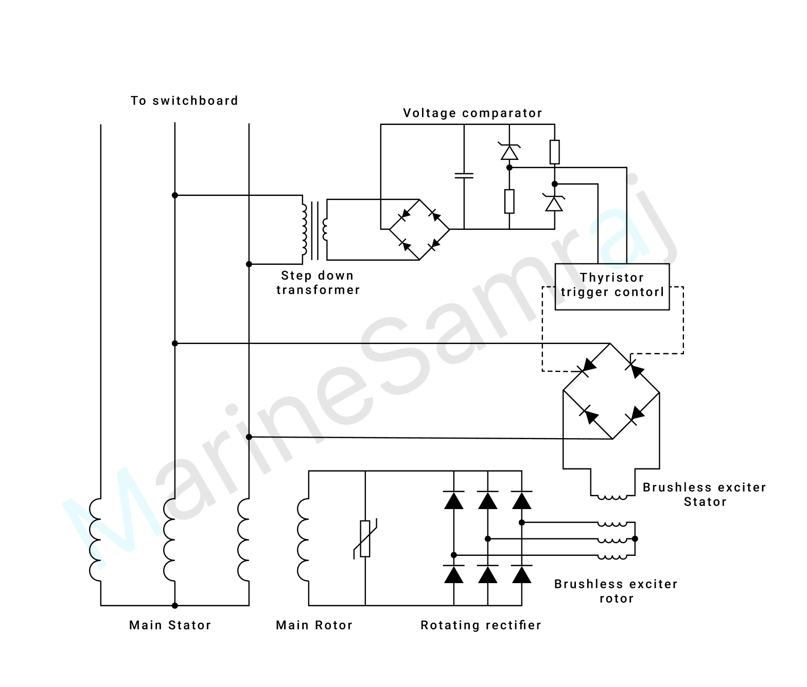
Sketch a circuit diagram for an Automatic Voltage Regulator illustrating how the A.V.R utilises a silicon-controlled rectifier to control the excitation system for an alternator. Describe how the A.V.R monitors output and controls the excitation system. (16)

Exam question diagram

Reference Answer

A simplified circuit diagram of a typical AVR is shown below. The generator terminal voltage is transformed to a suitable level, rectified and smoothed within the voltage measurement element, it is then fed into the comparator circuit consisting of two zener diodes and two resistors.
The comparator circuit produces an error signal which is fed into the thyristor trigger control unit. This signal controls the output of a pulse generator circuit, to fire a thyristor circuit and adjust the excitation level in the generator exciter field. In this way, generator voltage is restored to its correct level and the error voltage returns to near zero.
(can someone please add more information to the answer)
← Browse more questions

Prepare on Android — MeoMock on Google Play