← MeoMock / Written exams
ETO ETO Exam papers 📅 Feb 2023

Exam Question

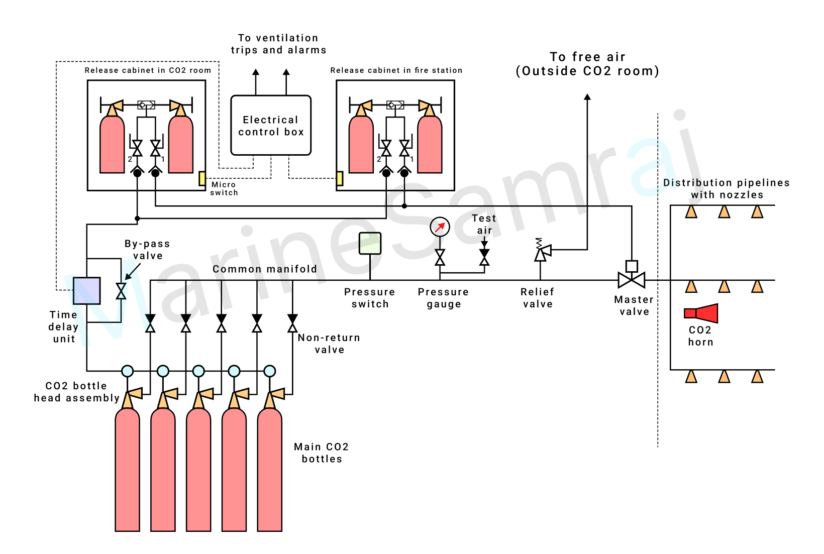
(a) Sketch and describe a total flooding CO2 gas system suitable for the protection of machinery spaces. (6)

(b) State, with reasons, which valve should be operated first in the system shown in (a) (4)

(c) State the periodic maintenance required on the system. (6)

Exam question diagram

Reference Answer

Main CO2 bottles contain carbon dioxide in liquid state with a pressure of 56 bar at 20°C. Pressure of CO2 at 25 and 30°C are 64 bar and 71 bar respectively. So it is important to keep the temperature of CO2 bottles low for limiting the pressure inside bottles. CO2 from the main bottle is released by a ‘CO2 release cabinet’ as shown in the figure. As soon as the release cabinet door is opened, a micro switch is activated. The micro switch will ensure the activation of CO2 warning alarms and ventilation shut off. CO2 release cabinet or release box consist of two pilot CO2 cylinders or bottles containing CO2 gas inside. The pressure of CO2 inside these pilot bottles is same as that of main CO2 bottles. Only quantity of gas is different. For releasing CO2 to the protected space, one of the pilot bottle valve is opened. Now CO2 reaches two valves marked 1 and 2. First valve 1 is to be opened. Then CO2 passes through a non-return valve and opens pneumatically operated master valve. Now master valve is opened. Next, open valve 2 in the release cabinet, which supply CO2 to main CO2 bottle head assembly through a non-return valve and ‘time delay unit’. Function of the time delay unit is explained below. Head assembly consist of a pressure operated cylinder valve. This pressure operated cylinder valve prevents CO2 from bottle coming to the common manifold. As CO2 reaches the head assembly from pilot bottle, pneumatic actuator in the head moves and opens the pressure operated cylinder valve. Then CO2 from main bottle escapes to the common manifold via non return valve as shown. Each of the main CO2 cylinder have a head assembly and non-return valve. The pilot CO2 line is connected to all these heads. All the CO2 from the main bottles now release to common manifold. Since the master valve is already open before, CO2 from manifold is released to the protected space through distribution pipe lines and nozzles.
As you can see in the diagram, there are two CO2 release cabinets. One is local release cabinet and is located in the CO2 room itself. One more remote release cabinet is used, which is located in a remote place such as fire control station. This facilitates operation of CO2 flooding system from a remote place other than CO2 room. Both release cabinets are connected in parallel and non-return valves fitted in the lines prevent back flow of CO2. Also two pilot CO2 bottles are placed in the release cabinet. Only one is sufficient for the operation of both master valve and CO2 bottle head assembly.
CO2 flooding system explained here protects only a single space. There are systems which can protect multiple spaces such as engine room and pump room together. In that case separate release cabinets will be there for engine room and pump room. Main CO2 bottles are shared for engine room and pump room according to the volume of the spaces.
← Browse more questions

Prepare on Android — MeoMock on Google Play